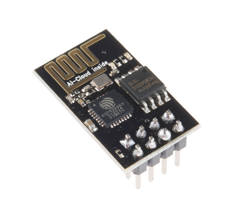
The ESP-01 module is a popular ESP8266 development board. Its popularity stems from its low cost and its small form factor. But one disadvantage of this board is the limited number of GPIO pins. Nevertheless, even with this very limited set of GPIOs, the ESP-01 can be connected with a Real Time Clock (RTC) module and a Liquid Crystal Display (LCD) using only two GPIO pins. That leaves the other two (2) GPIO pins available for other uses.
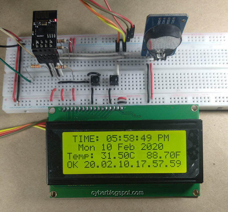
The digital clock shown above is made up of an ESP-01 ESP8266 module with the RTC module and the LCD display tied to GPIO-0 and GPIO-2 of the ESP-01. Not shown in the picture is the USB to TTL converter which is plugged on the PC and is also connected to the breadboard.
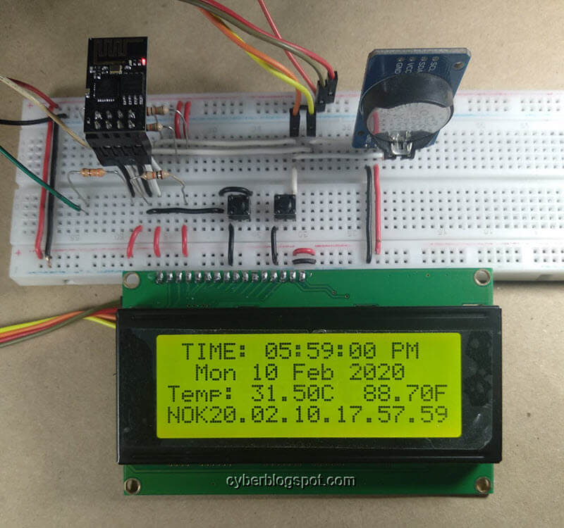
The digital clock displays the current time on the first row or the first line of the LCD display. The second line shows the current date. The third line contains the current temperature in Celsius and in Fahrenheit. The last line is the status line which displays the date and time of the last successful NTP synchronization of the clock. The status line also prints “OK” after a successful sync and changes to “NOK” when the clock needs an NTP sync or while awaiting for the next NTP clock sync to arrive.
On the software side, the clock is driven by the Time Library. With this library, synchronization by an RTC clock is as simple as providing a function which the library can call at a predetermined time interval.
1 | setSyncProvider(rtcGet); |
As an added feature, the RTC clock is synchronized by an NTP server. Since the ESP-01 module is WiFi capable, it is easy to connect to the Internet and request a Time server with the current timestamp.
1 | System Clock <== RTC Clock <== NTP Clock |
Requirements
- ESP-01 ESP8266 module
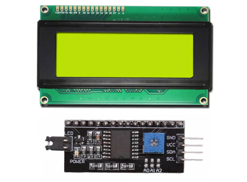
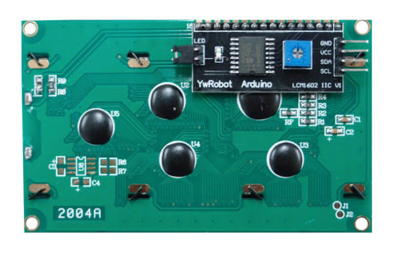
- LCD with I2C Interface
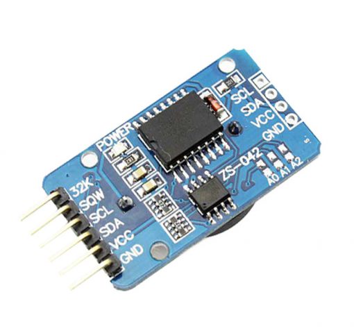
- Real Time Clock (RTC) module with I2C interface (DS3231 or DS3232)
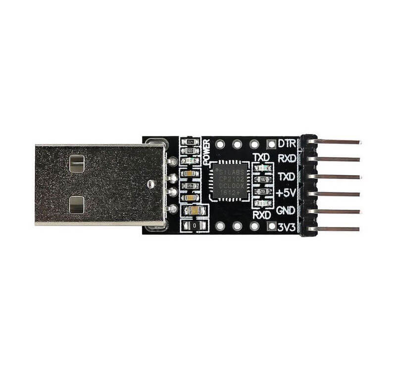
- USB to TTL converter
- 3 pieces 10K ohm 1/4W resistors
- 2 pieces pushbutton switches
- one optional 0.1 microfarad ceramic capacitor
- one optional 220 microfarad electrolytic capacitor
- breadboard and wires
Notes on Real Time Clock Modules
DS1302 and DS1307 RTC modules are both low precision clock modules. The reason is the frequency drift of the temperature-sensitive crystals used on these modules. Therefore, the recommended clock module is DS3231 which is more precise because the crystal is inside the DS3231 chip. This results in a better temperature tracking and frequency adjustment.
Also, DS3231 clock modules are sold at the same price as the DS1302 and DS1307 RTC modules.
The ESP-01 Flasher/Programmer
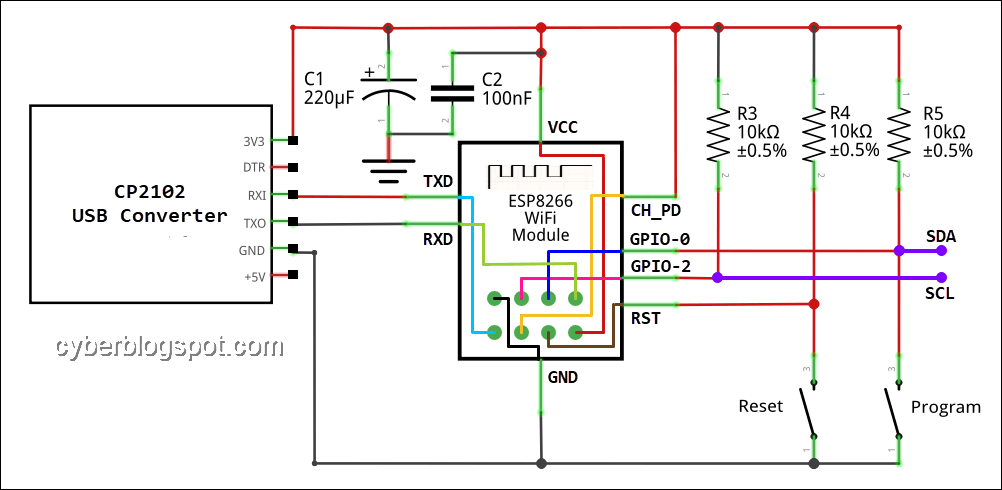
The ESP-01 ESP8266 module does not have a built-in flasher or flash memory programmer. So, it needs a programmer adapter. But when breadboarding, a better alternative than a programmer adapter is to connect the module with a USB to TTL converter. An example of such a circuit is shown in the schematic diagram above.
The USB to TTL converter’s Transmit (TXD) and Receive (RXD) terminals are connected to the ESP-01 module in a reverse manner. This means that the TXD terminal of the USB converter is connected to the RXD terminal of the ESP-01 module. In the same manner, the RXD terminal of the USB converter is connected to the ESP-01 module’s TXD terminal. The USB connector end of the USB to TTL converter goes to the USB port of a PC or a laptop.
Take note that the ESP-01 is being powered by the 3.3V output from the USB to TTL converter. For added power supply stability, an optional 220 microfarad electrolytic capacitor is connected on the power supply rails. Also, a 0.1 microfarad ceramic capacitor may be connected to reduce high-frequency interference from the power supply line. If possible, you should place the ceramic capacitor near the ESP-01 power terminals.
The three (3) 10K resistors are used as pull-up resistors. These pull-up resistors ensure that the ESP8266 pins are at their expected states. For example, during reset, ESP8266 expects the GPIO-2 to be at a HIGH state.
Pressing the Reset pushbutton switch will restart the ESP-01 module and will boot and run the program loaded or installed in the flash memory. In order to put the ESP-01 module into flash programming mode, press and hold the Program switch, press and release the Reset switch, and finally release the Program switch.
The SDA terminal which is connected to GPIO-0 and the SCL terminal that is connected to GPIO-2 is where the LCD module and the RTC module’s corresponding SDA and SCL terminals will connect.
LCD Module Connection
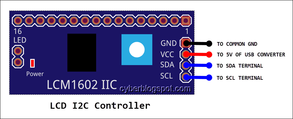
The LCD module’s I2C controller is connected to the Flasher/Programmer’s circuit thru the SDA and SCL terminals. The LCD module needs a 5 Volts supply so it must be connected to the USB to TTL converter’s 5V output.
RTC Module Connection
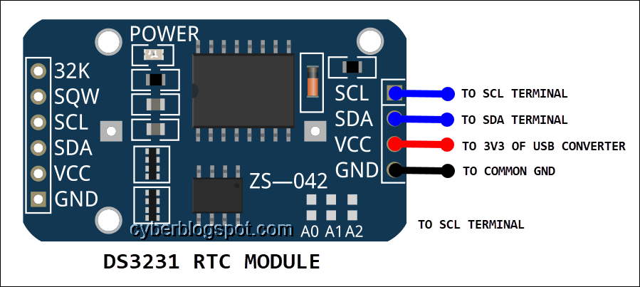
Connect the Real Time Clock (RTC) module to the same SDA and SCL terminals of the Flasher/Programmer. Basically, the LCD controller and the RTC module share the same I2C bus. Put in another way, their SDA and SCL pins are wired in parallel. Remember that the DS3231 RTC may be operated with 5 Volts or 3.3 Volts power supply. In this case, it is better to connect it to the 3.3 Volts output of the USB to TTL converter since the ESP-01 is also using the 3.3 Volts supply.
Programming the ESP-01 with RTC and LCD Display
We will be using the Arduino IDE to program the ESP-01, so you must already have it installed on your computer. If you need help in installing the Arduino IDE in Windows 10, please see: How to Install Arduino IDE on Windows 10.
Also, you need to install the ESP8266 Arduino Core in order to program ESP8266 based development boards on the Arduino IDE. Please take a look at the article How to Set Up Arduino IDE for ESP8266 Programming.
If your ESP-01 module is new or fresh from the factory, and you have not loaded any Arduino sketch on it, it still contains the factory-supplied AT Command Firmware. Loading an Arduino sketch or programming it with the Arduino IDE WILL ERASE the existing AT Command firmware.
You may want to backup the original firmware prior to programming your ESP-01 module. The backup firmware will come in handy in troubleshooting your ESP-01 module when it starts acting up. Learn how to save and restore ESP8266 firmware.
Sample Arduino IDE Sketch: ESP-01 with RTC and LCD Display
The sample Arduino sketch is a digital clock with two sync sources, the RTC clock and the Network Time Protocol (NTP). The digital clock uses the system clock which is synchronized by the RTC clock . The RTC clock is in turn synchronized by the NTP time.
Include Libraries
1 2 | #include <ESP8266WiFi.h> #include <WiFiUdp.h> |
The ESP8266Wifi library and the WiFiUdp library are built-in libraries of ESP8266 Arduino Core. If you selected the proper board, “Generic ESP8266 Module” under the menu Tools -> Board, you don’t need to download these two libraries.
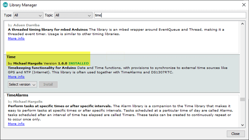
1 | #include <TimeLib.h> |
Time library by Michael Margolis Version 1.6.0. This library is maintained on Github by Paul Stoffregen. You may download it directly from Github, but it is advisable to use the Tools -> LIbrary Manager to install it, so that it will go the proper directory automatically.
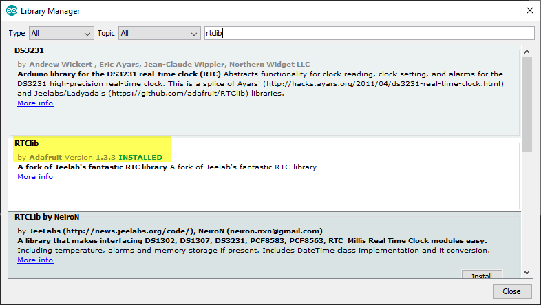
1 | #include <RTClib.h> |
There are many libraries for the DS3231 RTC module but this specific library is what we need. This library has support for I2C communication over ordinary GPIO pins of ESP8266. Download this library using the Tools -> LIbrary Manager.
1 | #include <LiquidCrystal_I2C.h> |
This is also a special library that supports I2C communications on GPIO-0 and GPIO-2 pins of ESP8266. Download from the provided link and put the decompressed library folder under Documents > Arduino > libraries if you’re using Windows 10: agnunez/ESP8266-I2C-LCD1602.
The complete library include is:
1 2 3 4 5 | #include <ESP8266WiFi.h> #include <WiFiUdp.h> #include <TimeLib.h> #include <RTClib.h> #include <LiquidCrystal_I2C.h> |
Initialization
1 2 3 4 5 6 7 8 9 10 11 12 13 14 15 16 17 18 19 20 21 22 23 24 25 26 27 28 | const char ssid[] = "ssid"; // your network SSID (name) const char pass[] = "password"; // your network password // NTP Servers: static const char ntpServerName[] = "ntp.pagasa.dost.gov.ph"; //static const char ntpServerName[] = "us.pool.ntp.org"; //static const char ntpServerName[] = "time.nist.gov"; //static const char ntpServerName[] = "time-a.timefreq.bldrdoc.gov"; //static const char ntpServerName[] = "time-b.timefreq.bldrdoc.gov"; //static const char ntpServerName[] = "time-c.timefreq.bldrdoc.gov"; const int timeZone = 8; //const int timeZond = 1; // Central European Time //const int timeZone = -5; // Eastern Standard Time (USA) //const int timeZone = -4; // Eastern Daylight Time (USA) //const int timeZone = -8; // Pacific Standard Time (USA) //const int timeZone = -7; // Pacific Daylight Time (USA) WiFiUDP Udp; unsigned int localPort = 8888; // local port to listen for UDP packets LiquidCrystal_I2C lcd(0x27, 20, 4); RTC_DS3231 rtc; time_t lastNtp; // last successful NTP sync #define ntpInterval 60 //for testing 60 seconds //could be daily or weekly as we're using //a precise rtc clock module |
In the above code fragment, you need to provide your router’s SSID and password so that the ESP-01 module can connect to the internet. Select the NTP server you want to use for synchronizing the RTC clock by defining ntpServerName. Next, provide the timezone constant applicable to your location.
The Network Time Protocol uses the UDP protocol, so a Udp object is created and a localport is assigned.
Functions
The NTP code below is lifted from the Time Library example.
The function sendNTPpacket() is responsible for the assembly and sending of the NTP time request packet via UDP protocol.
1 | void sendNTPpacket(IPAddress &address) |
The main NTP code is the getNTPTime() function.
1 | time_t getNtpTime() |
It calls the sendNTPpacket() function to send the NTP time request and waits for a maximum of 1500 milliseconds for a reply from the NTP server. If a reply from the NTP server is received within 1.5 seconds, it decodes the NTP reply packet and returns the adjusted timestamp to the program calling the getNtpTime() function.
However, if the function getNtpTime() did not get a reply from the NTP server after 1.5 seconds, the function would time out and it would return the value of zero (0) to the calling program. Remember to check the return value of getNtpTime(), making sure it’s not zero (0), before using it. Or else, you may end up resetting your clock to zero which is the start of the Unix Epoch (0:0:0, January 1, 1970).
1 2 3 4 5 6 7 8 9 10 11 12 13 14 15 16 17 18 19 20 21 22 23 24 25 26 27 28 29 30 31 32 33 34 35 36 37 38 39 40 41 42 43 44 45 46 47 48 49 50 51 52 53 54 55 56 57 58 | /*-------- NTP code ----------*/ const int NTP_PACKET_SIZE = 48; // NTP time is in the first 48 bytes of message byte packetBuffer[NTP_PACKET_SIZE]; //buffer to hold incoming & outgoing packets time_t getNtpTime() { IPAddress ntpServerIP; // NTP server's ip address while (Udp.parsePacket() > 0) ; // discard any previously received packets //Serial.println("Transmit NTP Request"); // get a random server from the pool WiFi.hostByName(ntpServerName, ntpServerIP); //Serial.print(ntpServerName); //Serial.print(": "); //Serial.println(ntpServerIP); sendNTPpacket(ntpServerIP); uint32_t beginWait = millis(); while (millis() - beginWait < 1500) { int size = Udp.parsePacket(); if (size >= NTP_PACKET_SIZE) { //Serial.println("Receive NTP Response"); Udp.read(packetBuffer, NTP_PACKET_SIZE); // read packet into the buffer unsigned long secsSince1900; // convert four bytes starting at location 40 to a long integer secsSince1900 = (unsigned long)packetBuffer[40] << 24; secsSince1900 |= (unsigned long)packetBuffer[41] << 16; secsSince1900 |= (unsigned long)packetBuffer[42] << 8; secsSince1900 |= (unsigned long)packetBuffer[43]; return secsSince1900 - 2208988800UL + timeZone * SECS_PER_HOUR; } } return 0; // return 0 if unable to get the time } // send an NTP request to the time server at the given address void sendNTPpacket(IPAddress &address) { // set all bytes in the buffer to 0 memset(packetBuffer, 0, NTP_PACKET_SIZE); // Initialize values needed to form NTP request // (see URL above for details on the packets) packetBuffer[0] = 0b11100011; // LI, Version, Mode packetBuffer[1] = 0; // Stratum, or type of clock packetBuffer[2] = 6; // Polling Interval packetBuffer[3] = 0xEC; // Peer Clock Precision // 8 bytes of zero for Root Delay & Root Dispersion packetBuffer[12] = 49; packetBuffer[13] = 0x4E; packetBuffer[14] = 49; packetBuffer[15] = 52; // all NTP fields have been given values, now // you can send a packet requesting a timestamp: Udp.beginPacket(address, 123); //NTP requests are to port 123 Udp.write(packetBuffer, NTP_PACKET_SIZE); Udp.endPacket(); } |
The Setup Function
1 2 3 4 5 6 7 8 9 10 11 12 | void setup() { lcd.begin(0, 2); // GPIO-0 SDA, GPIO-2 SCL lcd.backlight(); lcd.clear(); //Serial.begin(115200); syncRtc(); setSyncProvider(rtcGet); setSyncInterval(60); // 1 min for testing (default 300 - 5min) } |
The Loop Function
1 2 3 4 5 6 7 8 9 10 11 12 13 14 15 16 17 18 19 20 21 22 23 24 25 26 27 28 29 30 31 32 33 34 35 36 37 38 39 40 41 42 43 44 45 46 47 48 49 50 51 52 53 54 55 56 57 58 59 60 | void loop() { static time_t tLast; int h, m, s, y, mo, d, dow; time_t tNow = now(); if (tNow != tLast){ tLast = tNow; //h = hour(tNow); // 24-hour format h = hourFormat12(tNow); m = minute(tNow); s = second(tNow); y = year(tNow); mo = month(tNow); d = day(tNow); dow = weekday(tNow); // Print time on first line lcd.setCursor(1, 0); lcd.print("TIME: "); if (h < 10) lcd.print('0'); lcd.print(h); lcd.print(':'); if (m < 10) lcd.print('0'); lcd.print(m); lcd.print(':'); if (s < 10) lcd.print('0'); lcd.print(s); lcd.print(' '); if (isAM()) lcd.print("AM"); else lcd.print("PM"); //Print date on second line lcd.setCursor(2, 1); lcd.print(dayShortStr(dow)); lcd.print(' '); if (d < 10) lcd.print('0'); lcd.print(d); lcd.print(' '); lcd.print(monthShortStr(mo)); lcd.print(' '); lcd.print(y); //Print temperature on third line three lcd.setCursor(0, 2); lcd.print("Temp: "); float tempC = rtc.getTemperature(); float tempF = tempC * 9. / 5. + 32.; lcd.print(tempC); lcd.print('C'); lcd.print(" "); lcd.print(tempF); lcd.print('F'); } if (tNow >= lastNtp + ntpInterval){ syncRtc(); // sync RTC with NTP } } |
The Complete Sketch: ESP-01 with RTC and LCD Display
1 2 3 4 5 6 7 8 9 10 11 12 13 14 15 16 17 18 19 20 21 22 23 24 25 26 27 28 29 30 31 32 33 34 35 36 37 38 39 40 41 42 43 44 45 46 47 48 49 50 51 52 53 54 55 56 57 58 59 60 61 62 63 64 65 66 67 68 69 70 71 72 73 74 75 76 77 78 79 80 81 82 83 84 85 86 87 88 89 90 91 92 93 94 95 96 97 98 99 100 101 102 103 104 105 106 107 108 109 110 111 112 113 114 115 116 117 118 119 120 121 122 123 124 125 126 127 128 129 130 131 132 133 134 135 136 137 138 139 140 141 142 143 144 145 146 147 148 149 150 151 152 153 154 155 156 157 158 159 160 161 162 163 164 165 166 167 168 169 170 171 172 173 174 175 176 177 178 179 180 181 182 183 184 185 186 187 188 189 190 191 192 193 194 195 196 197 198 199 200 201 202 203 204 205 206 207 208 209 210 211 212 213 214 215 216 217 218 219 220 221 222 223 224 225 226 227 228 229 230 231 232 233 234 235 236 237 238 239 240 241 242 243 244 245 246 247 248 249 250 251 252 | /* ESP-01-LCD-RTC-NTP-Clock.ino * by Cyberblogspot 09Feb2020 * * NTP code is from Time Library: * TimeNTP_ESP8266WiFi.ino * Example showing time sync to NTP time source */ #include <ESP8266WiFi.h> #include <WiFiUdp.h> #include <TimeLib.h> #include <RTClib.h> #include <LiquidCrystal_I2C.h> const char ssid[] = "ssid"; // your network SSID (name) const char pass[] = "password"; // your network password // NTP Servers: static const char ntpServerName[] = "ntp.pagasa.dost.gov.ph"; //static const char ntpServerName[] = "us.pool.ntp.org"; //static const char ntpServerName[] = "time.nist.gov"; //static const char ntpServerName[] = "time-a.timefreq.bldrdoc.gov"; //static const char ntpServerName[] = "time-b.timefreq.bldrdoc.gov"; //static const char ntpServerName[] = "time-c.timefreq.bldrdoc.gov"; const int timeZone = 8; //const int timeZond = 1; // Central European Time //const int timeZone = -5; // Eastern Standard Time (USA) //const int timeZone = -4; // Eastern Daylight Time (USA) //const int timeZone = -8; // Pacific Standard Time (USA) //const int timeZone = -7; // Pacific Daylight Time (USA) WiFiUDP Udp; unsigned int localPort = 8888; // local port to listen for UDP packets LiquidCrystal_I2C lcd(0x27, 20, 4); RTC_DS3231 rtc; time_t lastNtp; // last successful NTP sync #define ntpInterval 60 //for testing 60 seconds //could be daily or weekly as we're using //a precise rtc clock module void setup() { lcd.begin(0, 2); // GPIO-0 SDA, GPIO-2 SCL lcd.backlight(); lcd.clear(); //Serial.begin(115200); syncRtc(); setSyncProvider(rtcGet); setSyncInterval(60); // 1 min for testing (default 300 - 5min) } void loop() { static time_t tLast; int h, m, s, y, mo, d, dow; time_t tNow = now(); if (tNow != tLast){ tLast = tNow; //h = hour(tNow); // 24-hour format h = hourFormat12(tNow); m = minute(tNow); s = second(tNow); y = year(tNow); mo = month(tNow); d = day(tNow); dow = weekday(tNow); // Print time on first line lcd.setCursor(1, 0); lcd.print("TIME: "); if (h < 10) lcd.print('0'); lcd.print(h); lcd.print(':'); if (m < 10) lcd.print('0'); lcd.print(m); lcd.print(':'); if (s < 10) lcd.print('0'); lcd.print(s); lcd.print(' '); if (isAM()) lcd.print("AM"); else lcd.print("PM"); //Print date on second line lcd.setCursor(2, 1); lcd.print(dayShortStr(dow)); lcd.print(' '); if (d < 10) lcd.print('0'); lcd.print(d); lcd.print(' '); lcd.print(monthShortStr(mo)); lcd.print(' '); lcd.print(y); //Print temperature on third line three lcd.setCursor(0, 2); lcd.print("Temp: "); float tempC = rtc.getTemperature(); float tempF = tempC * 9. / 5. + 32.; lcd.print(tempC); lcd.print('C'); lcd.print(" "); lcd.print(tempF); lcd.print('F'); } if (tNow >= lastNtp + ntpInterval){ syncRtc(); // sync RTC with NTP } } /* * void syncRtc() * * Connects to the internet in non-blocking mode * * Once connected, gets the NTP time, synchronizes the RTC clock, * and disconnects from the internet * * Displays the last successfull NTP sync date and time * Prints NOK if RTC needs sync or OK after a successful sync * */ bool pendingConnect = false; void syncRtc(){ if (!pendingConnect){ WiFi.begin(ssid, pass); pendingConnect = true; } if (WiFi.status() == WL_CONNECTED){ pendingConnect = false; Udp.begin(localPort); time_t tNow = getNtpTime(); //returns 0 on fail if (tNow != 0) { rtc.adjust(DateTime(tNow)); lastNtp = tNow; lcd.setCursor(0, 3); lcd.print("OK "); // Display lastNtP on fourth line of LCD int y, mo, d, h, m, s; y = year(lastNtp)-2000; mo = month(lastNtp); d = day(lastNtp); h = hour(lastNtp); m = minute(lastNtp); s = second(lastNtp); lcd.setCursor(3, 3); lcd.print(y); lcd.print('.'); if (mo < 10) lcd.print('0'); lcd.print(mo); lcd.print('.'); if (d < 10) lcd.print('0'); lcd.print(d); lcd.print('.'); if (h < 10) lcd.print('0'); lcd.print(h); lcd.print('.'); if (m < 10) lcd.print('0'); lcd.print(m); lcd.print('.'); if (s < 10) lcd.print('0'); lcd.print(s); // For battery operation, test ESP8266 sleep mode WiFi.disconnect(); WiFi.mode(WIFI_OFF); } } else { lcd.setCursor(0,3); // not yet connected, exit promptly lcd.print("NOK"); // we'll try on the next loop } } // Sync provider function time_t rtcGet(){ return rtc.now().unixtime(); } /*-------- NTP code ----------*/ const int NTP_PACKET_SIZE = 48; // NTP time is in the first 48 bytes of message byte packetBuffer[NTP_PACKET_SIZE]; //buffer to hold incoming & outgoing packets time_t getNtpTime() { IPAddress ntpServerIP; // NTP server's ip address while (Udp.parsePacket() > 0) ; // discard any previously received packets //Serial.println("Transmit NTP Request"); // get a random server from the pool WiFi.hostByName(ntpServerName, ntpServerIP); //Serial.print(ntpServerName); //Serial.print(": "); //Serial.println(ntpServerIP); sendNTPpacket(ntpServerIP); uint32_t beginWait = millis(); while (millis() - beginWait < 1500) { int size = Udp.parsePacket(); if (size >= NTP_PACKET_SIZE) { //Serial.println("Receive NTP Response"); Udp.read(packetBuffer, NTP_PACKET_SIZE); // read packet into the buffer unsigned long secsSince1900; // convert four bytes starting at location 40 to a long integer secsSince1900 = (unsigned long)packetBuffer[40] << 24; secsSince1900 |= (unsigned long)packetBuffer[41] << 16; secsSince1900 |= (unsigned long)packetBuffer[42] << 8; secsSince1900 |= (unsigned long)packetBuffer[43]; return secsSince1900 - 2208988800UL + timeZone * SECS_PER_HOUR; } } return 0; // return 0 if unable to get the time } // send an NTP request to the time server at the given address void sendNTPpacket(IPAddress &address) { // set all bytes in the buffer to 0 memset(packetBuffer, 0, NTP_PACKET_SIZE); // Initialize values needed to form NTP request // (see URL above for details on the packets) packetBuffer[0] = 0b11100011; // LI, Version, Mode packetBuffer[1] = 0; // Stratum, or type of clock packetBuffer[2] = 6; // Polling Interval packetBuffer[3] = 0xEC; // Peer Clock Precision // 8 bytes of zero for Root Delay & Root Dispersion packetBuffer[12] = 49; packetBuffer[13] = 0x4E; packetBuffer[14] = 49; packetBuffer[15] = 52; // all NTP fields have been given values, now // you can send a packet requesting a timestamp: Udp.beginPacket(address, 123); //NTP requests are to port 123 Udp.write(packetBuffer, NTP_PACKET_SIZE); Udp.endPacket(); } |
Download Source Code: ESP-01 with RTC and LCD Display
Related Articles on ESP-01 with RTC and LCD Display
Hardware
How to Program ESP-01 with Arduino IDE
NodeMCU ESP32S Pin Configuration
NodeMCU V3 ESP8266 Pinout and Configuration
How to Save and Restore ESP8266 and ESP32 Firmware
How to Test NodeMCU V3 Using Esptool
How to Connect a DS3231 to NodeMCU V3
Software
How to Install Arduino IDE on Windows 10
How to Set up Arduino IDE for ESP8266 Programming
How to Install Esptool on Windows 10