To program an ESP-01 module with Arduino IDE, the module needs to be connected to a programmer adapter. What keeps the ESP-01 module apart from other ESP8266-based microcontroller modules is the absence of a UART interface. Hence, a programmer adapter is required or it can be wired with a USB to TTL converter to create a programmer.
ESP-01 Programmers
ESP-01 USB-to-Serial Converter Programmer Module
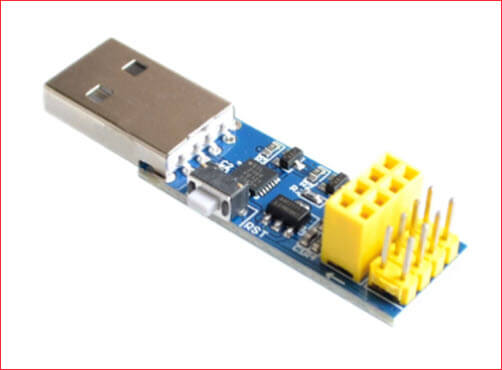
The ESP-01 programmer module shown in Figure 1 uses the Silabs CP2104 USB-to-serial converter chip. Other ESP-01 programmer modules use the CH340 chip. With this kind of programmer module, you do not have to worry about switching the ESP-01 module from RUN mode to PROGRAMMING mode. ESP-01 modules have what we call boot modes (see Table 1 below). That is, when they are powered up or when they are reset, depending on the state of the GPIO0 pin, they either RUN the program on their flash memory or enter into PROGRAMMING mode. With the programmer module above, everything is automatic. The ESP-01 module automatically switches into PROGRAMMING mode when you hit the Upload button on the Arduino IDE.
DIY USB-to-serial Converter Programmer
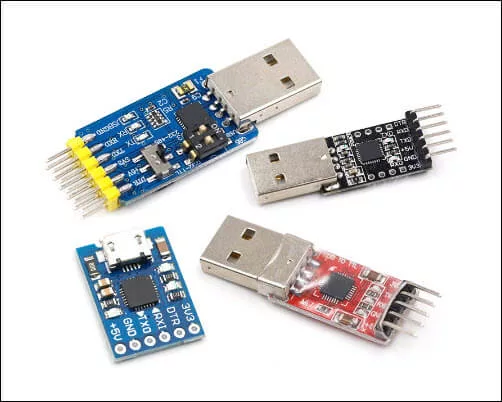
If you do not have an ESP-01 USB-to-serial converter programmer module, you can make your own programmer if you have a USB-to-serial converter. Figure 2 shows some examples of USB-to-serial converters.
Below is an schematic diagram of an ESP-01 programmer using a USB to TTL converter module. This is the preferred ESP-01 programmer while breadboarding because all the ESP-01 pins are accessible.
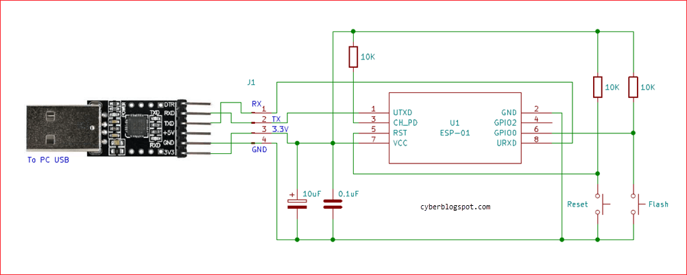
About the Circuit
The three (3) 10k resistors are pull-up resistors necessary to ensure that the ESP8266 pins are on their proper logic levels. The two capacitors are optional components to increase the stability of the programmer. The 10 microfarad capacitor serves as an additional ac ripple filter while the 0.1 microFarad (100 nanoFarad) capacitor is used as high-frequency filter.
The RESET and PROGRAM switches are push-button switches. Pressing and then releasing the RESET switch will boot and run the program loaded in the flash memory. Pressing and releasing the RESET switch, while at the same time holding down the PROGRAM switch, will place the ESP-01 into the UART Bootloader mode, or go into programming mode. See the table below.
Again, the sequence of switch presses in order to go into programming mode is: press and hold down the PROGRAM switch, press and release the RESET switch, and finally release the PROGRAM switch.
Boot Mode Table
| GPIO-2 | GPIO-0 | Boot Mode |
| HIGH | LOW | UART Bootloader (Programming Mode) |
| HIGH | HIGH | Run program in flash |
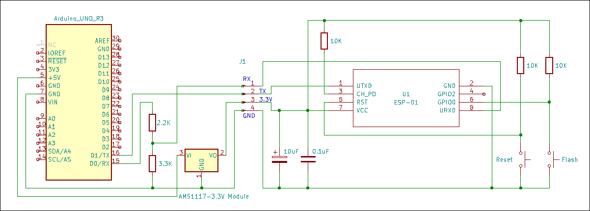
Arduino Board as ESP-01 Programmer
Another option for an ESP-01 programmer is an Arduino board. You can use any Arduino board available – Arduino Uno, Arduino Nano, Arduino Mega, etc. Figure 4 is an schematic diagram of an Arduino Uno board used as an ESP-01 programmer. Note that it is exactly the same schematic diagram shown in Figure 3, only with the USB-to-serial converter being replaced by an Arduino Uno board. For more information about using an Arduino board as ESP-01 programmer, please see – ESP-01 and ESP-01S Pinout and Configuration.
Programming using Arduino IDE
To program the ESP-01 using the Arduino IDE, the ESP8266 core for Arduino must first be installed. Please see, How to Set up Arduino IDE for ESP8266 Programming.
If you don’t have the Arduino IDE installed yet, and you’re using Windows 10, see: How to Install Arduino IDE on Windows 10.
The Blink Program
The first lesson for programming the ESP-01 with the Arduino IDE is the Blink sketch. Open the Arduino IDE, create a new sketch, then, copy and paste the Blink program below.
1 2 3 4 5 6 7 8 9 10 | void setup() { pinMode(LED_BUILTIN, OUTPUT); // Initialize the LED_BUILTIN pin as an output } // the loop function runs over and over again forever void loop() { digitalWrite(LED_BUILTIN, LOW); // Turn the LED on (Built-in LED on ESP-01 is active LOW) delay(1000); // Wait for a second digitalWrite(LED_BUILTIN, HIGH); // Turn the LED off by making the voltage HIGH delay(2000); // Wait for two seconds (to demonstrate the active low LED) } |
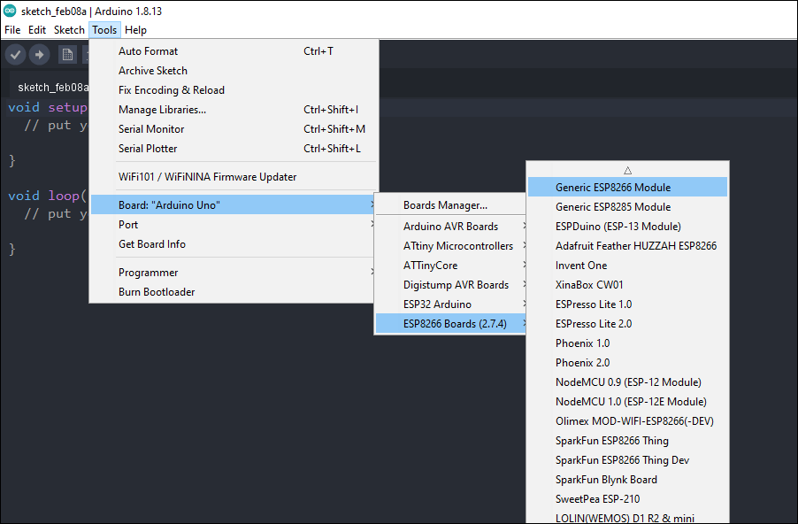
Before uploading the sketch to the ESP-01 module, first, make sure that you have selected the right board which is “Generic ESP8266 Module”. Please refer to Figure 5.
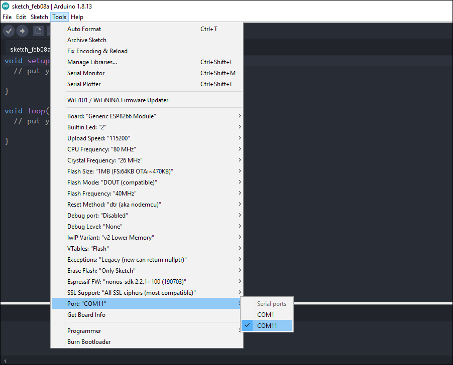
Also, make sure that the appropriate serial COM port for your ESP-01 programmer is selected. If it is your first time to use your ESP-01 programmer, you may have to install the device driver for your ESP-01 programmer.
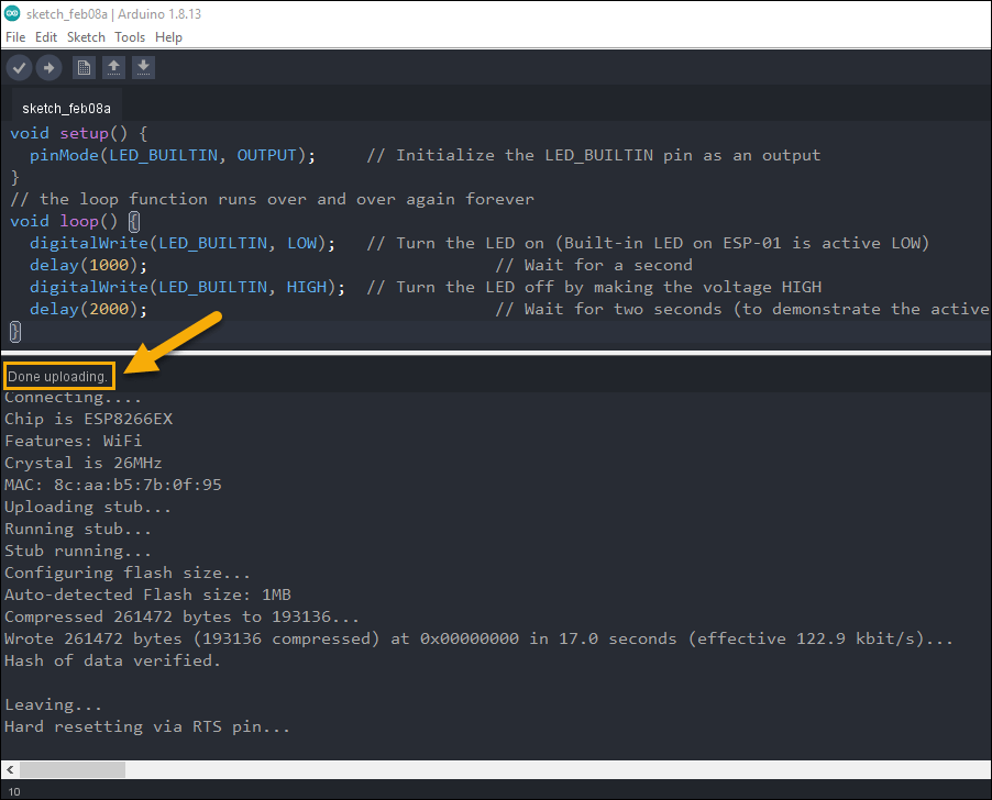
After selecting the right board and the correct serial COM port, click the Upload button. Following a successful upload with the message “Done uploading” (see Figure 7), the blue built-in LED on your ESP-01 board should start flashing.
If the LED does NOT flash, you must be using a different version of ESP-01 module. You may have to change the “Built-in LED:” setting on the Arduino IDE. If you want to know why, please see the article entitled Difference Between ESP-01 and ESP-01S.
How to Program ESP-01 with Arduino IDE to Control an LED with Smartphone
One of the popular uses of ESP-01 module is in IoT (Internet of Things) applications. The ESP-01 module can be used to control a switch (relay) remotely or wirelessly through Wi-Fi. This enables any device (light, motor, etc.) connected to the relay to be turned on and off remotely. To learn more on how to implement this, see the following articles.
Related Articles on How to Program ESP-01 with Arduino IDE
Arduino Reference and Resources
How to Set up Arduino IDE for ESP8266 Programming
NodeMCU V3 ESP8266 Pinout and Configuration
How to Test NodeMCU V3 Using Esptool
How to Install Arduino IDE on Windows 10
How to Save and Restore ESP8266 and ESP32 Firmware
NodeMCU ESP-32S Pin Configuration
How to Use MCP4725 Module with Arduino
How to Use ADS1220 ADC Module with Arduino
Capacitor shown on the schematic 100 nf is not same as you said, 100 pf.
@Kerim Bekir, you were right, there was some typo error on the capacitor. The value in the schematic diagram is correct: 100nF or 0.1uF.
As additional info, it is a standard practice to use a 0.1uF (100nF) and a 10uF capacitors as power supply decoupling capacitors. The bigger 10uF capacitor filters the low frequency while the smaller 0.1uF capacitor is for the high frequency. The values are adjusted depending on the situation. A good article on the topic can be found here, https://components101.com/articles/decoupling-capacitor-vs-bypass-capacitors-working-and-applications.