There are many competing but compatible ESP32 microcontroller development boards. As a result of the competition, different ESP32 board models have different pin configurations. It is therefore imperative to properly identify your ESP32 compatible board and use the correct pin configuration guide. This NodeMCU ESP-32S pinout and configuration is for the ESP32 development board with the backside shown below.
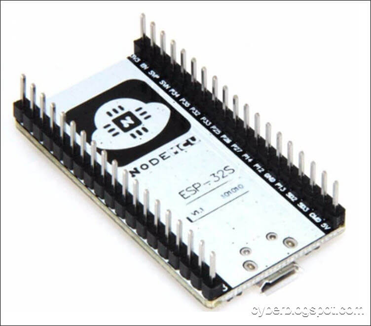
As can be seen from the picture above, it’s very hard to make a mistake in identifying the board if you look at the underside. It is clearly marked NodeMCU ESP-32S and at the very top of the board is a big Ai-Thinker logo.

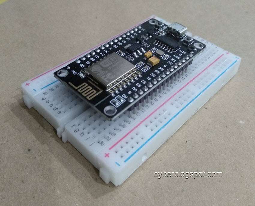
Now, let’s take a closer look at the top side of the ESP-32S board. Take note that this particular ESP32 development board DOES NOT HAVE any pin labels on the top side. Take another look at the backside and you will find the pin labels there. If you insert this board on a breadboard, how, for God’s sake, can you see the pin labels? Start breadboarding with this ESP-32S board and you’ll know what i mean. To search for a particular pin, you will need to count the pins from either side of the board.
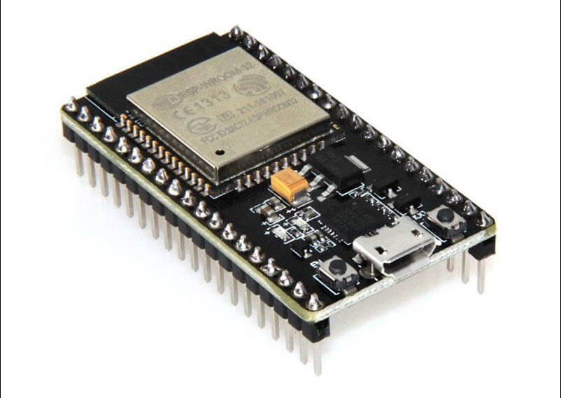
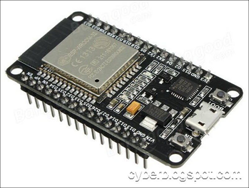
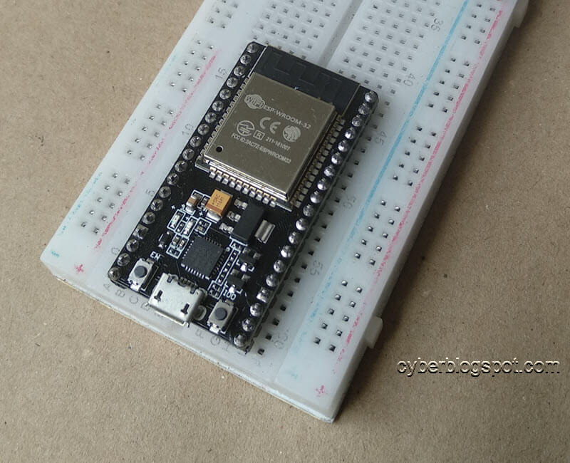
You would probably wish you had bought another board like this:
Why does NodeMCU ESP-32S have no pin labels?
It is due to the board’s small form factor. The NodeMCU ESP-32S board is narrower than the DOIT ESP-32 board shown above. If pin labels were printed on the top side of the ESP-32S board, they would probably be too small to be legible.
And why, in the first place, did Ai-Thinker used a smaller form factor that prevented it from printing legible pin labels?
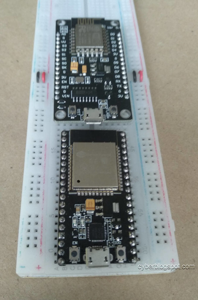
The reason is that the wider form factor covers the whole width of the breadboard.
In order to use this board having a larger form factor, you need to saw off and split your breadboard into two, like this:
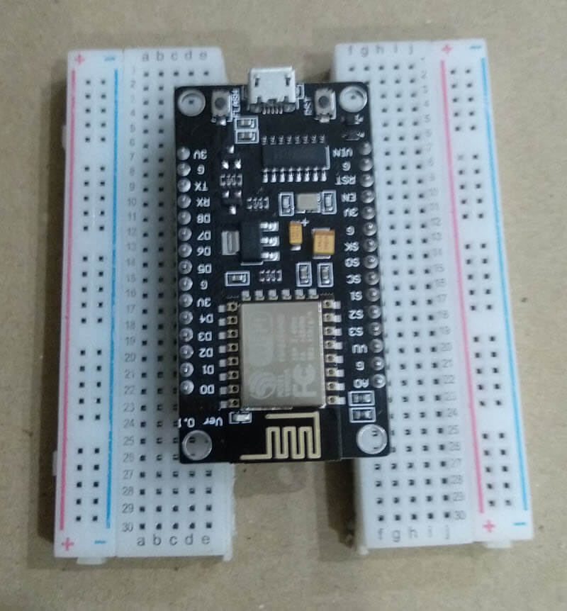
In contrast, a narrower board leaves a row of breadboard pins on both sides of the board. And as a result, you don’t need to literally hack your breadboard.
How to Make Breadboarding NodeMCU ESP-32S Easier
As I was looking for a Fritzing part download in order to make my own pin configuration guide for NodeMCU ESP-32S, I came across this page. I am reproducing it here just in case we lost the page.
The OP (original poster) in the Fritzing forum created a pin configuration template that we can print and lay on top of the breadboard. This facilitates breadboarding, without the need to count the pins left or right when breadboarding.
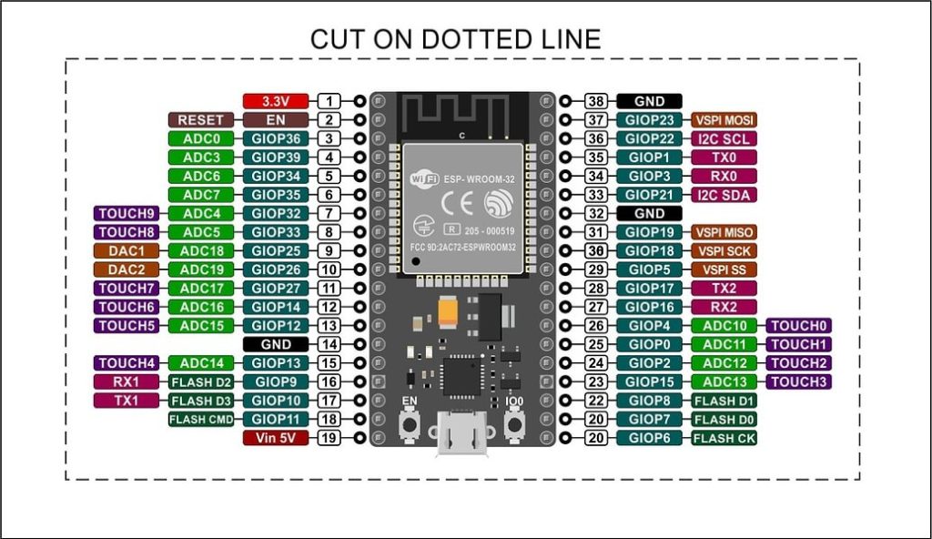
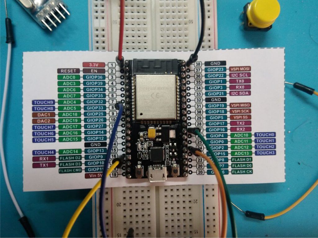
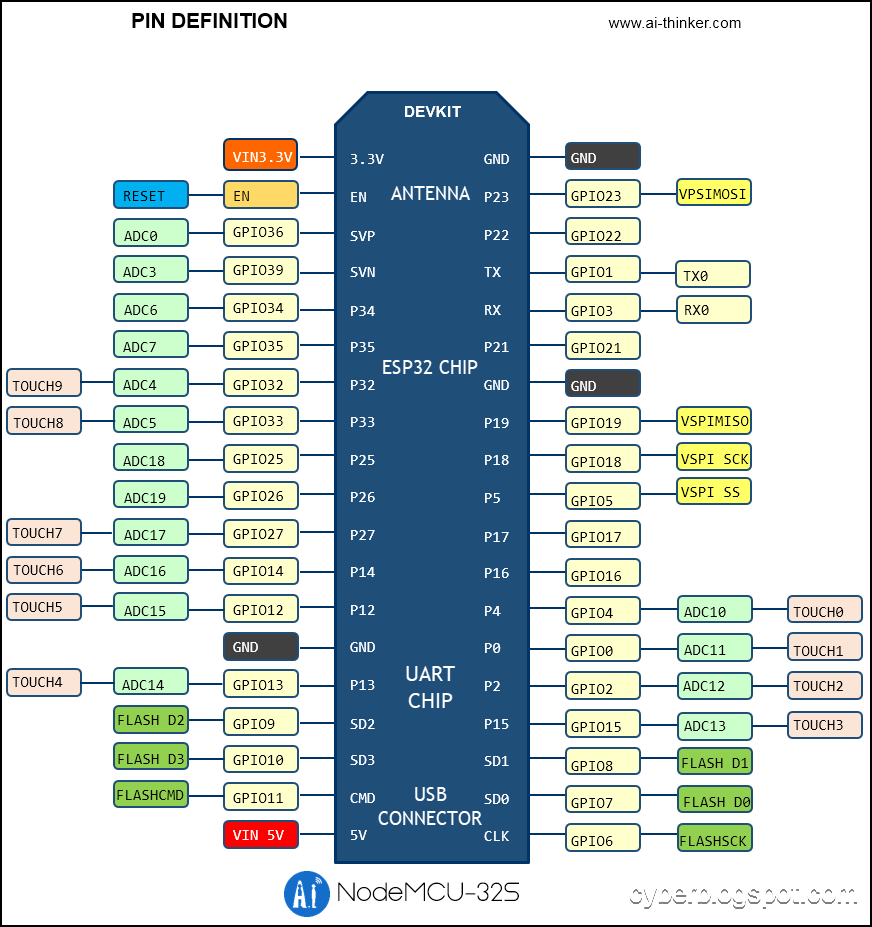
Below is the edited NodeMCU ESP-32S pin configuration from the manufacturer.
Related Articles on NodeMCU ESP-32S Pinout and Configuration
ESP8266 and ESP32
How to Set up Arduino IDE for ESP8266 Programming
How to Save and Restore ESP8266 and ESP32 Firmware
NodeMCU V3 ESP8266 Pinout and Configuration
How to Test a NodeMCU V3 ESP8266 Dev Board
ESP-01
How to Program ESP-01 with Arduino IDE
ESP-01 and ESP-01S Pinout and Configuration
Difference Between ESP-01 and ESP-01S
How to Test an ESP-01 ESP8266 Module
How to Control ESP-01 thru a Router
How to Control ESP-01 Without a Router
How to Use ESP-01 Wi-Fi Relay Module
ESP-01 with RTC and LCD Display
ESP-01 ESP8266 NTP Clock with LCD Display
ATtiny85
How to Install ATTinyCore on Arduino IDE
How to Program ATtiny85 with Arduino IDE
How to Program Digispark ATtiny85 Board with Arduino IDE
Digispark ATtiny85 Pinout and Configuration
How to Enable Serial Monitor on Digispark ATtiny85
How to Use Arduino as ISP Programmer
Bluetooth
How to Use AT-09 BLE with Arduino and Smartphone
O thank God you have the pinout with I2C for the Lua version.
I just couldn’t find it anywhere.
Thank you for sharing !
THANK YOU!!!
Finally I found it.very detail explanation. I very appreciated it