
An Arduino auto ranging ohmmeter is easy to implement using an Arduino Uno or other Arduino development boards. And depending on the implementation, it can rival the accuracy of commercial digital ohmmeters available in the market.
To better appreciate an auto ranging Arduino ohmmeter, let us first create a simple ohmmeter using an Arduino Uno development board. After studying the underlying theory behind its operation, we will assemble a more accurate, full-pledged auto ranging ohmmeter.
The Simple Arduino Ohmmeter
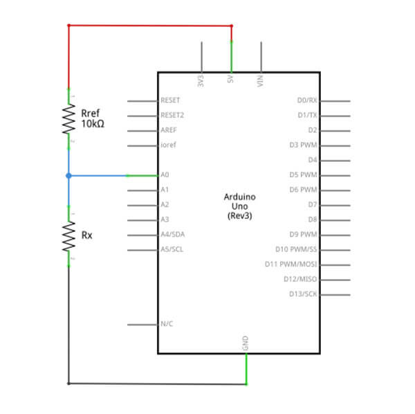
A simple Arduino ohmmeter schematic diagram is shown below. It uses an Arduino Uno development board and a 10kΩ reference resistor (Rref) in series with the resistor being tested (Rx).
The following Arduino IDE sketch will display the value of the unknown resistor Rx on the Arduino IDE’s serial monitor.
|
1 2 3 4 5 6 7 8 9 10 11 |
#define Rref 10000.0 void setup() { Serial.begin(9600); } void loop() { uint16_t x = analogRead(A0); float Rx = Rref * x/(1024 - x); Serial.println(Rx); delay(2000); } |
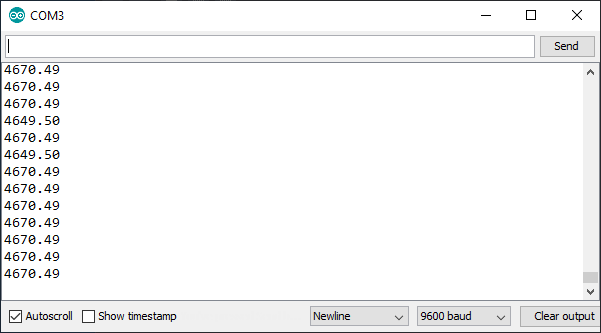
Here is a screenshot of the output of the sketch shown above. A resistor with a value of 4.7kΩ and a tolerance of 1% was used as Rx. The output shows a value of 4.670kΩ. However, it sometimes fluctuates to 4.649kΩ. The measured value looks close enough to the actual value of the resistor. Considering that a 1% tolerance is equal to 47Ω, we expect to get a value between 4.653kΩ and 4.747kΩ.
Prelude to Arduino Auto Ranging Ohmmeter
How is resistance measured?
In an Arduino ohmmeter, the unknown resistance of a resistor is measured indirectly using Ohm’s Law.
The Current (I) flowing into a circuit is equal to the impressed Voltage (V) divided by the circuit Resistance (R).
Ohm’s Law

Using the above equation, if we know the voltage (V) across the resistor and the current (I) flowing through it, we can calculate its resistance value.
The voltage (V) across the resistor is easily measured by connecting it to the ADC (Analog to Digital Converter) pin of an Arduino development board. But we need a way to calculate the Current (I) flowing thru it so we can compute the Resistance R.
The Voltage Divider Circuit – Computing the Current (I)
There is a technique used to compute the current (I) thru an unknown resistor. The technique involves placing another resistor with a known value in series with the unknown resistor. The resulting circuit is known as a Voltage Divider Circuit. Please see Figure 4 below.
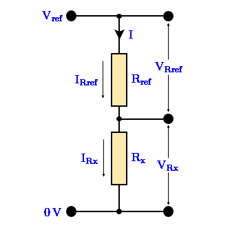
In the voltage divider circuit above, Rref is the resistor of a known value and Rx is the unknown resistor being measured. VRx will be read and measured by an ADC, hence, let us assume that this is a known voltage.
The input voltage Vref is divided between the two resistors in series, Rref and Rx. Therefore,
and the voltage VRref across the known resistor Rref is,
Since Rref is of a known resistance and we already know the voltage across it, we can now compute the value of IRref, the current passing thru it.
The current IRref is the same current flowing thru the unknown resistor Rx. So, it follows that,
Finally, to compute the resistance of the unknown resistor, Rx, we substitute Equation 0.4 in the resistance formula below.
Rearranging Equation 0.5, we get the final equation for computing Rx.
Analog to Digital Converter – Measuring Voltage Across the Resistor
The voltage across the resistor being measured is fed to the ADC of an Arduino development board. Arduino Uno’s ADC has a resolution of 10 bits or 210, which is equal to 1024. This means that the reference voltage for the ADC is divided by 1024. Representing the ADC output reading with the variable x, VRx can be computed using the formula:
Also, given the value of VRx, which is the input to the ADC, we can find the value of x by using the formula:
Caveat:
The Arduino’s Due, Zero and MKR Family boards have 12-bit ADC capabilities but are by default set to 10-bit resolution. If they are run in 12-bit resolution by calling analogReadResolution(12), the constant 1024 must be replaced with 4096.
See Reference on analogReadResolution()
Using Equation 1 and Equation 2.0 as mentioned above, we can compute the value of the unknown resistor Rx if we have the ADC output reading x.
In an Arduino IDE sketch, we may use the following code to compute the value of Rx:
|
1 2 3 4 5 |
#define Rref 10000.0 void setup() { uint16_t x = analogRead(A0); float Vrx = x * 5.0/1024 //compute voltage across resistor float Rx = Rref * Vrx /(5.0-Vrx); //compute resistance |
Computing Rx as a Function of x
The Equation 1 above for computing the value of the unknown resistor Rx is based on a pre-computed value of VRx. Actually there is a more simple formula for figuring out the value of Rx. The output value x of the ADC can be used to directly compute Rx. The formula is:
Notice the similarity of Equation 1 & Equation 3. The voltages, Vref and VRx, were simply replaced with their equivalent ADC values.
Let’s do a little exercise. We’ll try to prove that Equation 1 and Equation 3 are indeed equal to each other.
First, using the voltage divider circuit in Figure 2, the value of the voltage VRx (again using Ohm’s Law) is,
VRx is fed into the ADC, so we can use Equation 2,
Equating Equation 4 and Equation 2.0, we have,
Using the cross multiplication method,
Move Vref and 1024 to the right side of the equation.
Cancel out Vref.
We need to remove the variable Rx that is on the right side of the equation. Multiply the terms of the numerator and then separate the two terms.
Move the second term containing the variable Rx to the left side of the equation.
Factor out Rx.
Multiplying both sides of the equation with 1024, we get,
Finally move the term in the parenthesis to the right side of the equation.
This shows that we can directly use the ADC output x, which is the value from the analogRead() function, to compute the value of Rx without the need to compute the value of VRx.
The Ohmmeter Accuracy
Referring to Figure 4 above, let’s compute VRx in terms of the two series resistors.
Now, assume the following resistor values: Rref = 10KΩ and Rx = 10KΩ. Let’s compute VRx using Equation 4.
Compute x using Equation 2.1.
Let us do the same computation for the values of Rref = 10KΩ and Rx = 1KΩ.
Again, compute for Rref = 10KΩ and Rx = 100Ω.
Using the three (3) computed ADC values, compute Rx using Equation 3.
Below is a table of the above computations.
| Rref | Rx (Actual) | VRx | ADC (x) | Rx (Computed) |
| 10kΩ | 10kΩ | 2.5V | 512 | 10.00kΩ |
| 10kΩ | 1kΩ | 0.4545V | 93 | 0.9989kΩ |
| 10kΩ | 100Ω | 0.0495V | 10 | 98.6Ω |
If you compare column 2, Rx (Actual) and column 5, Rx (Computed) of the table shown above, you will notice that there are discrepancies between the actual Rx values and the computed Rx values of row 2 and row 3. Only the first row has the exact value of the computed Rx value. Also, take note that row 2 has a lower discrepancy compared to row 3.
To clearly see the problem, let us take a second set of computations. This time, instead of a 10kΩ Rref, let’s use a value of 1kΩ for Rref.
Rref = 1kΩ and Rx = 10kΩ
====================================
Rref = 1kΩ and Rx = 1kΩ
====================================
Rref = 1kΩ and Rx = 100Ω
Here is the table for the second set of computations.
| Rref | Rx (Actual) | VRx | ADC (x) | Rx (Computed) |
| 1kΩ | 10kΩ | 4.545V | 931 | 10.01K |
| 1kΩ | 1kΩ | 2.5V | 512 | 1.00K |
| 1kΩ | 100Ω | 0.4545V | 93 | 99.89 Ohms |
Studying the two tables will highlight the facts about the voltage divider circuit being used to measure the resistance of the unknown resistor Rx.
- The most accurate measurement of the value of Rx occurs when Rx and Rref are equal.
- The higher the difference of the values of Rx and Rref, the less accurate the measurement will be.
To reduce the error in the measurement of resistance, a solution is to use different values for Rref. It can be implemented by manually switching reference resistors from a bank of resistors during a measurement.
Or better yet, automatically select and switch the proper value of Rref electronically, and controlled by software. That leads us to an Arduino auto ranging ohmmeter.
Arduino Auto Ranging Ohmmeter, Part 2
Related Articles on Arduino Auto Ranging Ohmmeter
Hardware
NodeMCU ESP32S Pin Configuration
NodeMCU V3 ESP8266 Pinout and Configuration
How to Save and Restore ESP8266 and ESP32 Firmware
How to Test NodeMCU V3 Using Esptool
How to Connect a DS3231 to NodeMCU V3
Software
How to Install Arduino IDE on Windows 10
How to Set up Arduino IDE for ESP8266 Programming
How to Install Esptool on Windows 10
References on Arduino Auto Ranging Ohmmeter
Ohmmeter Using Arduino – circuitstoday.com – diode in series with reference resistors
Arduino Based Auto-Ranging Ohmmeter – simple-circuit.com – transistor switch
Resistomatic – an Arduino-based autoranging ohm-meter -blog.rareshool.com – simple resistor bank, no diodes, no transistors
Arduino Digital Multimeter
How accurate is an Arduino Ohmmeter?
Why ADC/1024 is correct, and ADC/1023 is just plain wrong!
Online Equation Writer